JFF45
-
Posts
34 -
Joined
-
Last visited
-
Days Won
10
Recent Profile Visitors
3,763 profile views


JFF45's Achievements
")


-
I was able to repair my conversion thread by opening an Imgur account to host the pics but f they do the same as PB I won't bother repairing again.
-
The pics were hosted by Photobucket but they no longer allow it so I've deleted my account there. As I moved to a TD42 I didn't keep the pics.
-
 Rumcajs reacted to a post in a topic:
RE4R03A Nomad valve body overhaul
Rumcajs reacted to a post in a topic:
RE4R03A Nomad valve body overhaul
-
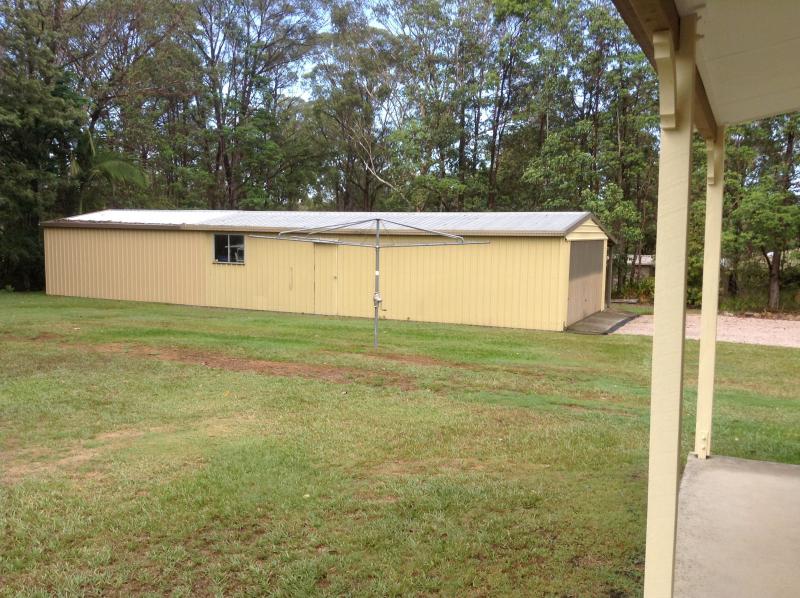
It's in a 6 metre extension I built onto an existing shed. I needed the workshop space and still have room to keep 2 cars. I couldn't get the same coloured tin. The original shed was 20 years old. See the faded door..

-
It's a shed job alright. Here's where I'm doing the trans
-
Yep, it's always an anxious moment when you turn the key after fitting it. It wouldn't take much to get something wrong if you weren't paying attention..
-
BigGQWesty reacted to a post in a topic:
RE4R03A Nomad valve body overhaul
-
Rumcajs reacted to a post in a topic:
RE4R03A Nomad valve body overhaul
-
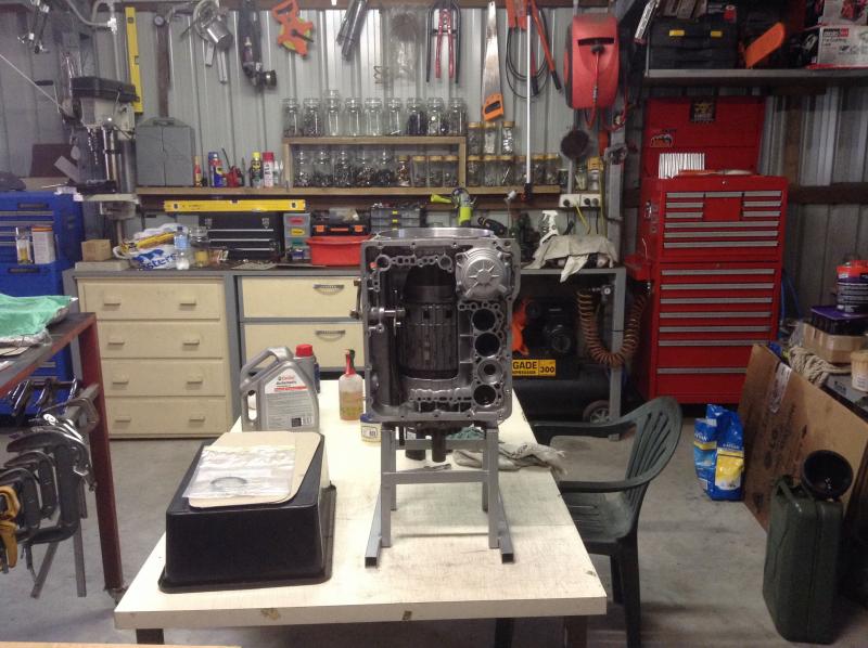
I know this will have limited interest but I noticed that the RE4R03A rebuild threads don't go into much detail on how to overhaul the valve body. This one happens to be a Nomad valve body that I bought used from a trans that had suffered an oil pump mishap so it had to be completely dismantled to make sure it was spotless. First you need to print out the relevant pages of the FSM and preferably put them under plastic. I also have the pages for the full trans overhaul in there as well. Prepare a nice clear workspace for yourself. I have this fairly big steel leg laminated table I got from the dump for $10. I used black plastic initially but it didn't like the ATF so I had to work directly on the table. It's really important when doing this kind of work, where parts need to go back in the correct order, to have some way of clearly and logically laying out those parts. I simply cut a length of aluminium flashing (Bunnings) and used some stainless rods I had to form a corrugated sheet. It bends easily by hand and takes 5 minutes to make. Simply follow the FSM and you can't go wrong. Wholesale Autos, who supply these valve bodies, make there own laser cut separator plate. Most shift kit makers (TransGo, Superior, etc) supply drill bits to modify the plate so this is obviously a more professional approach. The upper body has the majority of the valves so we start there. The pressure regulator (2nd from top) almost certainly has been modified judging by the red coloured spring. Most shift kits modify it as well. 5th from the top and 3rd from the bottom are machined parts that don't match the FSM. These are called Shuttle shift valves and originally they move against a spring with an end plug for the locking pin. These have the pin slot machined in the ends so they are effectively locked solid which is the obvious reason they no longer have a spring either. Here's a clearer pic of the parts.. Then we do the lower body. Same system, line the bits up in the corrugations in the order and sequence in which they're removed. I've now fitted this valve body to my TB45E in place of the valve body in which I fitted a TransGo shift kit a few years ago. This one might be slightly more precise in the 2-3 change but there's not much difference otherwise. A TransGo shift kit can be bought for ~$140 and I think the Nomad exchange valve bodies are now > $1000. I'm currently doing a complete rebuild of a RE4R03A from a TB45E but I'm building it to Infinity Q45 (the 4.5 lt V8) specs with the extra clutches. I'll do a thread with pics when I've finished it.
-
Rumcajs reacted to a post in a topic:
Thermostatic fan install to 2000 zd30 intercooler How to do it correctly
-
 Here's an option for IC fan control. http://www.autospeed.com/cms/A_112617/article.html It's what I'll be using for the IC fan control for my turbo install. I found one on Ebay for a little over $20 delivered..
 -
tb45e camshaft pos (12) error
JFF45 replied to rodneyb81's topic in Nissan Patrol GU/Y61 (GU Patrol, 1999–2016)
TB45E MAF rarely have issues. If you have an Ecutalk, you can log a run and check voltages. I have some Excel files with logged MAF data, also have some graphs I did of RPM vs MAF. Also have a spare MAF here if you need to try another one before buying. -
Rumcajs reacted to a post in a topic:
DIY - Winch mount + winch install with alloy bumper
-
Rumcajs reacted to a post in a topic:
DIY - Winch mount + winch install with alloy bumper
-
Rumcajs reacted to a post in a topic:
DIY - Winch mount + winch install with alloy bumper
-
Rumcajs reacted to a post in a topic:
DIY - Winch mount + winch install with alloy bumper
-
DIY - Winch mount + winch install with alloy bumper
JFF45 replied to JFF45's topic in DIY Modifications & Accessories
Cheers guys, hope it's useful for others. -
admin reacted to a post in a topic:
DIY - Winch mount + winch install with alloy bumper
-
Just thought I'd add some pics of fittings on the turbo. I initially used an adapter for the oil feed with the 1mm restrictor (as shown a bit earlier) but I was never really happy with the number of connectors needed to guide the feed line in. This is what I mean - there's the adapter/restrictor then a F to F -4AN elbow (couldn't find F to M) then a M to M union to be able to fit the elbow from the feed line. Then I found this the other day.. a banjo fitting with the 1mm restrictor in the banjo bolt and a -4AN inlet. This is also a much lower profile and allows a lot better access to one of the T3 flange nuts. With the previous connectors, I had to clock the turbo a couple of degrees more to make sure I could get a socket onto the flange nut. Here's a pic of how all the fittings should be as seen from the block side. The oil feed is much neater now. The water cooling will be also be banjo fittings with -6AN cones (also from Kinugawa) and the oil drain is -10AN. I've seen installations where rubber hoses have been used for both the water cooling and the oil drain but the teflon braided hoses and fittings are not a lot more expensive if you source them from Ebay and make them yourself. They certainly look a lot better..
-
DIY - Winch mount + winch install with alloy bumper
JFF45 replied to JFF45's topic in DIY Modifications & Accessories
Cheers mate, I appreciate your comments -
GQ Beast reacted to a post in a topic:
DIY - Winch mount + winch install with alloy bumper
-
Good, useful info! I seem to recall it was also advised to place a disconnected airbag on a solid floor (outside the vehicle, of course) with the vinyl side up.
-
As I mentioned at the start of this thread, I'm running an auto trans with this project and I added a Davies Craig cooler for the trans fluid. This involved relocating one half of the power steering cooler from the right to the left side and I thought it might be of interest to others how cheaply this can be done. For those using a manual box, this might also be a handy mod if they want to mount a radiator for a W2A IC. This is the standard layout on a TB45E.. ..and this is what we want to achieve: These are aluminium tubes and I have nothing to weld them.. and they are probably too thin for the average amateur to attempt to weld anyway. As luck would have it, the tubes are just the right size for these 1/2 brass plumbing elbows with the nylon olives.. You just need to be able to silver solder a short length of copper tube with 2 copper elbows to join this part here: I decided to retain the original trans cooler and connect it in series with the new Davies Craig. I had to move the original ~25mm forward. This is the finished mod. I've been running it now for over 6 months and not the slightest sign of an issue. There's very little pressure there anyway. From memory, cost of the brass elbows for this mod was <$15.. This is the cooler I used. Bought from Ebay. The highest temp reading I've seen since is 80C. Before the extra cooler I could get it to ~105C so a turbo installation definitely needs this mod. Standard temp on the highway with the TC locked is between 60 & 70C which is almost a little too cool. I'm also planning on removing the cooling pipes that run through the radiator. There has been more than one report of failure of these pipes resulting in mixing of trans fluid and coolant in both the trans and the engine.
-
You can be sure that neither the Y62 owners nor the LC200 owners care much about those kinds of reports..
-
DIY - Winch mount + winch install with alloy bumper
JFF45 replied to JFF45's topic in DIY Modifications & Accessories
I discarded the original TI stainless barwork & bumper and found an alloy bar on Gumtree for $250. Now to fit the alloy bar and adjust the fairlead. I did the cutout for the fairlead with an air body saw fitted with a broken hacksaw blade. .. and no, the rope doesn't hang there now. It was just for the pic